Deploying the Streaming Integrator as a Minimum HA Cluster in AWS ECS
Introduction
This section explains how to run WSO2 Streaming Integrator as a minimum HA (High Availability) cluster in AWS (Amazon Web Services) ECS(Elastic Container Service).
The minimum HA cluster typically has two nodes where one node operates as the active node and the other as the passive node. Each node maintains a communication link with the other node as well as with the database.
Assigning the Active and Passive statuses to nodes
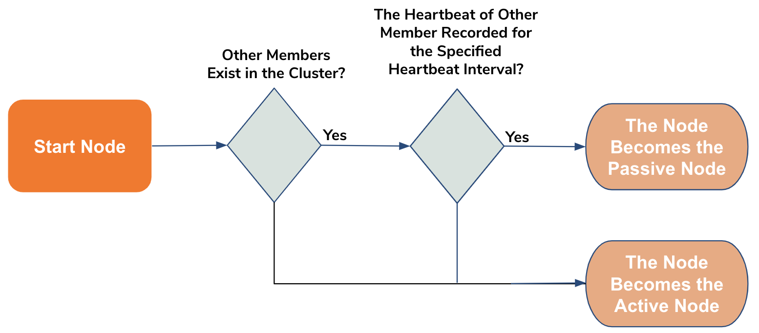
When a node is started in the minimum HA cluster mode, it checks the tables in the WSO2_CLUSTER_DB database. This check covers checking whether there are existing members in the cluster. If other nodes already exist as members of the cluster, it checks whether there are heartbeats from the existing member(s) for the last time interval that is of the same length as the specified heartbeat interval. If no heartbeat exists for the specified time interval, the node is added to the cluster as the active node. If not, it is added as the passive node.
Once a node becomes the active node, it performs the following:
- Inserts its own details in the
WSO2_CLUSTER_DBdatabase or updates them if they already exist. The details includenodeId,clusterGroup,propertyMap, andheartbeatTimestamp. - Periodically updates the appropriate table of the
WSO2_CLUSTER_DBdatabase with its heartbeat (timestamp). - Starts the Siddhi applications in runtime and opens all the ports mentioned in the Siddhi applications.
- Starts the binary and thrift transports.
- Starts the REST endpoints.
- Once a new member (i.e., passive node) joins the cluster, the active node checks the
WSO2_CLUSTER_DBdatabase for the host and port of ther other member's event syncing server. Once this information is retrieved, it sends the input events received by the cluster to that event syncing server.
Operating the nodes
When the cluster is running with both the nodes, the active node sends each event received by the cluster to the passive node's event sync server with the event timestamp. It also persists the state (windows, sequences, patterns, aggregations, etc.,) in the database named PERSISTENSE_DB.
Each time the state is persisted, the active node sends a control message to the passive node.
The passive node saves the events sent to its event sync server in a queue. When it receives the control message from the active node, it trims the queue to keep only the latest events that were not used by the active node to build the state of Siddhi applications at the time of persisting the state.
Handling the failure of the active node
The passive node continuously monitors the heartbeat of the active node. If the active node fails, the passive node follows the process shown below to start functioning as the active node so that data is not lost due to node failure.

The following table explains the above steps.
| Step | Description |
|---|---|
| 1. Start Siddhi Application Runtime | This is done without opening any ports mentioned in Siddhi applications. This is because the Siddhi application statuses need to be restored to what they were before the node failure so that unprocessed events before the failure are not lost. |
| 2. Restore State | This is done by retrieving the states persisted in the PERSISTENSE_DB database. |
| 3. Direct Events in Queue to Streams | The unprocessed events that are currently in the queue of the event sync server are directed into the relevant streams of the Siddhi applications. |
| 4. Open Ports, Binary & Thrift Transports, and REST Endpoints |
Once the above steps are completed, the previously passive and now active node opens the ports, starts the thrift and binary transports, and opens the REST endpoints. |
Setting up the SI cluster in AWS ECS
Before you begin:
In order to deploy WSO2 Streaming Integrator in AWS ECS, you need to complete the following requisites:
- create an account in AWS.
- Download and install AWS CLI Version 2.
- Download and install Docker. For instructions, see Docker Documentation.
Step 1: Store SI Docker images in ECR
-
Generate an access key and a secret key.
-
Sign in to the IAM console via the AWS console. Under Access Management, click Users.
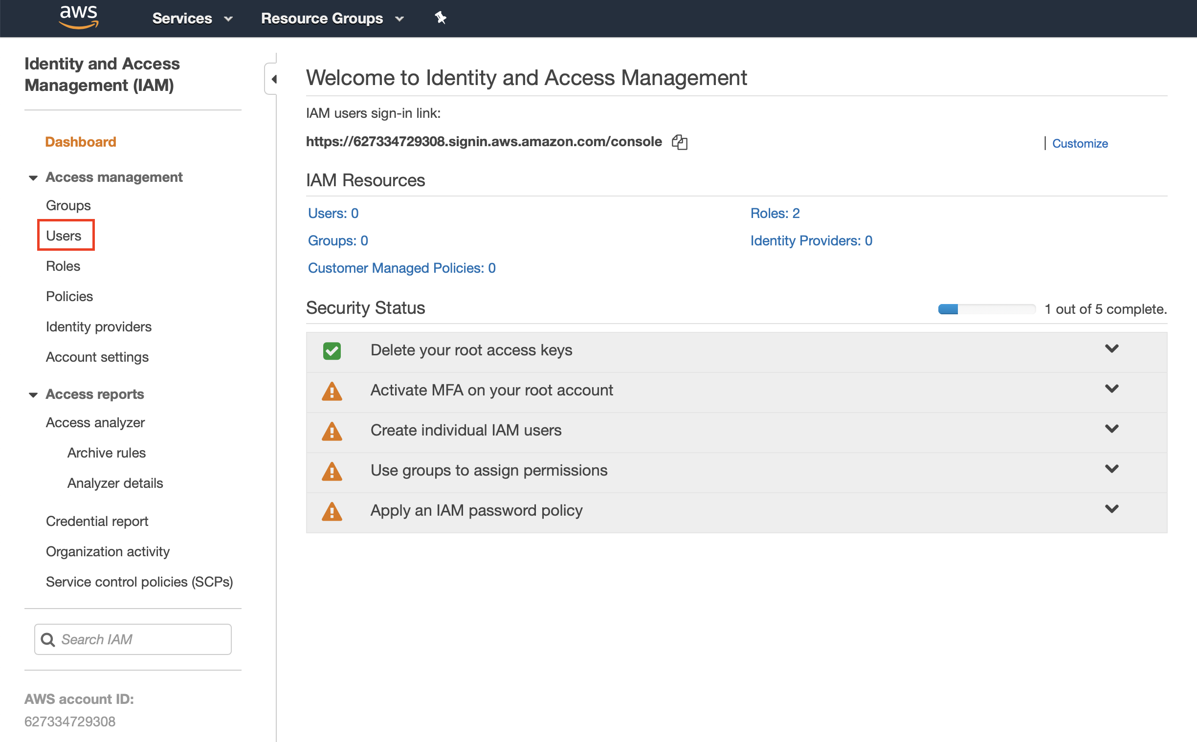
Then click Add User in the page that appears, and enter information as follows.
-
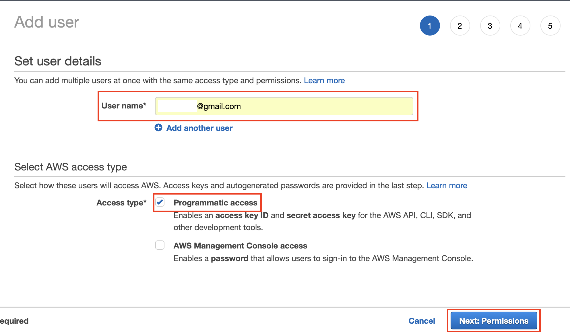
In the User name field, enter a valid email address. Under Access Type, select the Programmatic Access check box. Then click Next:Permissions.
-
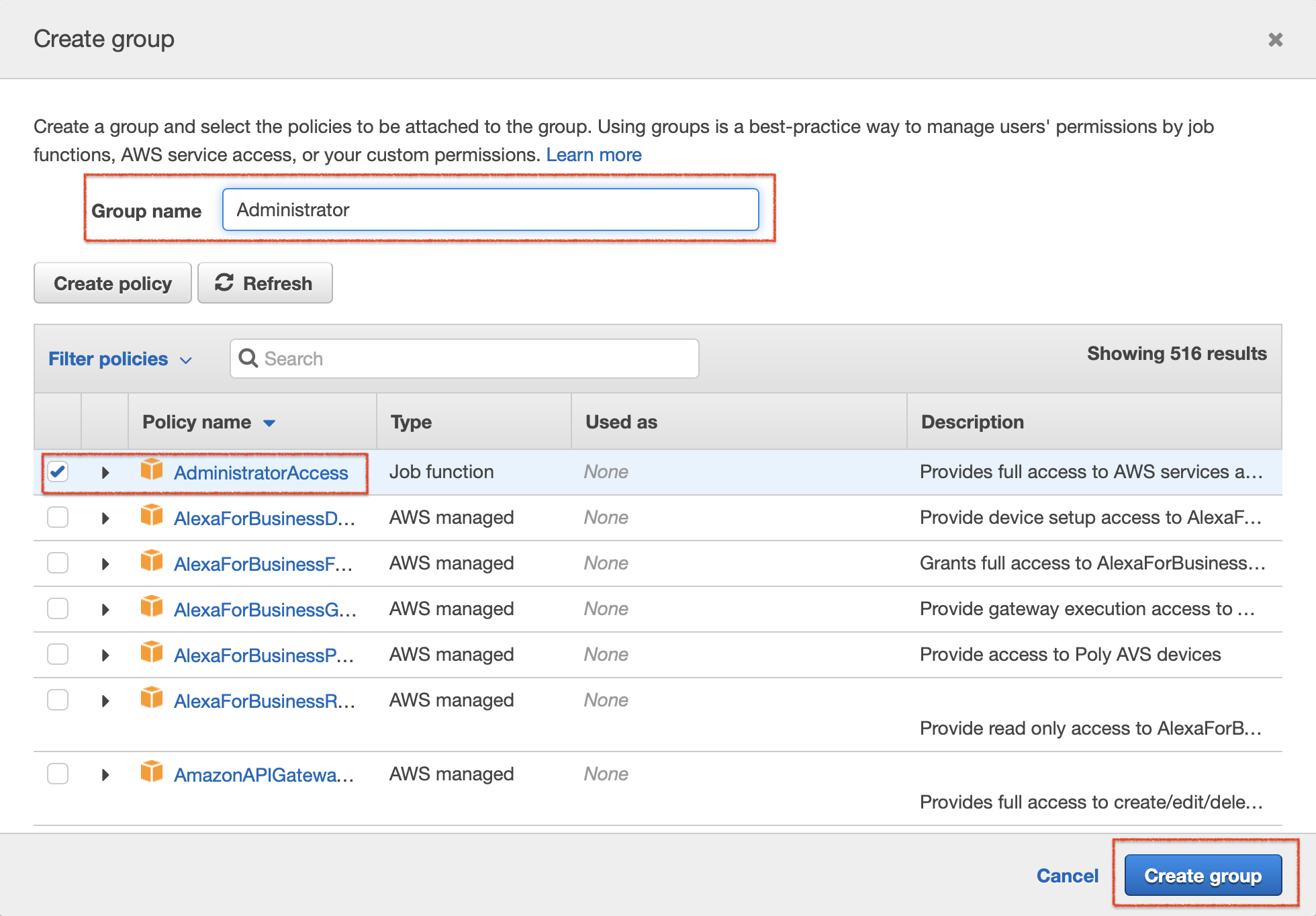
Add the user you are creating to a relevant group. In this example, let's create a new group. To do this, click Create Group and open the CreateGroup dialog box. Then enter a name for the group, select the AdministratorAccess check box, and then click Create Group.
Click Next:Tags, and in the next page click Next:Review.
-
Review the information you have entered for the user. If you want to change anything, go back to the relevant previous page. If not, click Create User to save the information and create the user.
Once you create the user, you can get the access key and the secret key as shown below.
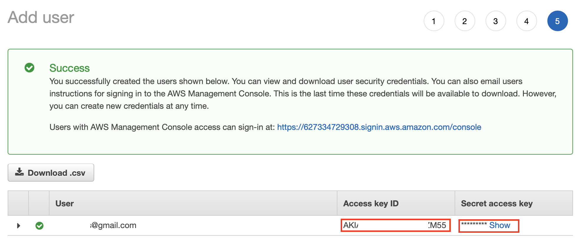
-
-
-
Issue the following command in the terminal to configure AWS.
aws configureYou are prompted for the
AWS Access Key ID,AWS Secret Access Key,Default region name, andDefault output format. For this example, you can enter the following values.Requested Information Value AWS Access Key IDEnter the access key that you generated when you created the AWS user. AWS Secret Access Key [None]Enter the secret key that you generated when you created the AWS user. Default region nameus-east-2.Default output formatjson -
Create a repository in the ECR (Elastic Container Registry).
-
Access AWS ECR (Elastic Container Registry) via the AWS Console.
-
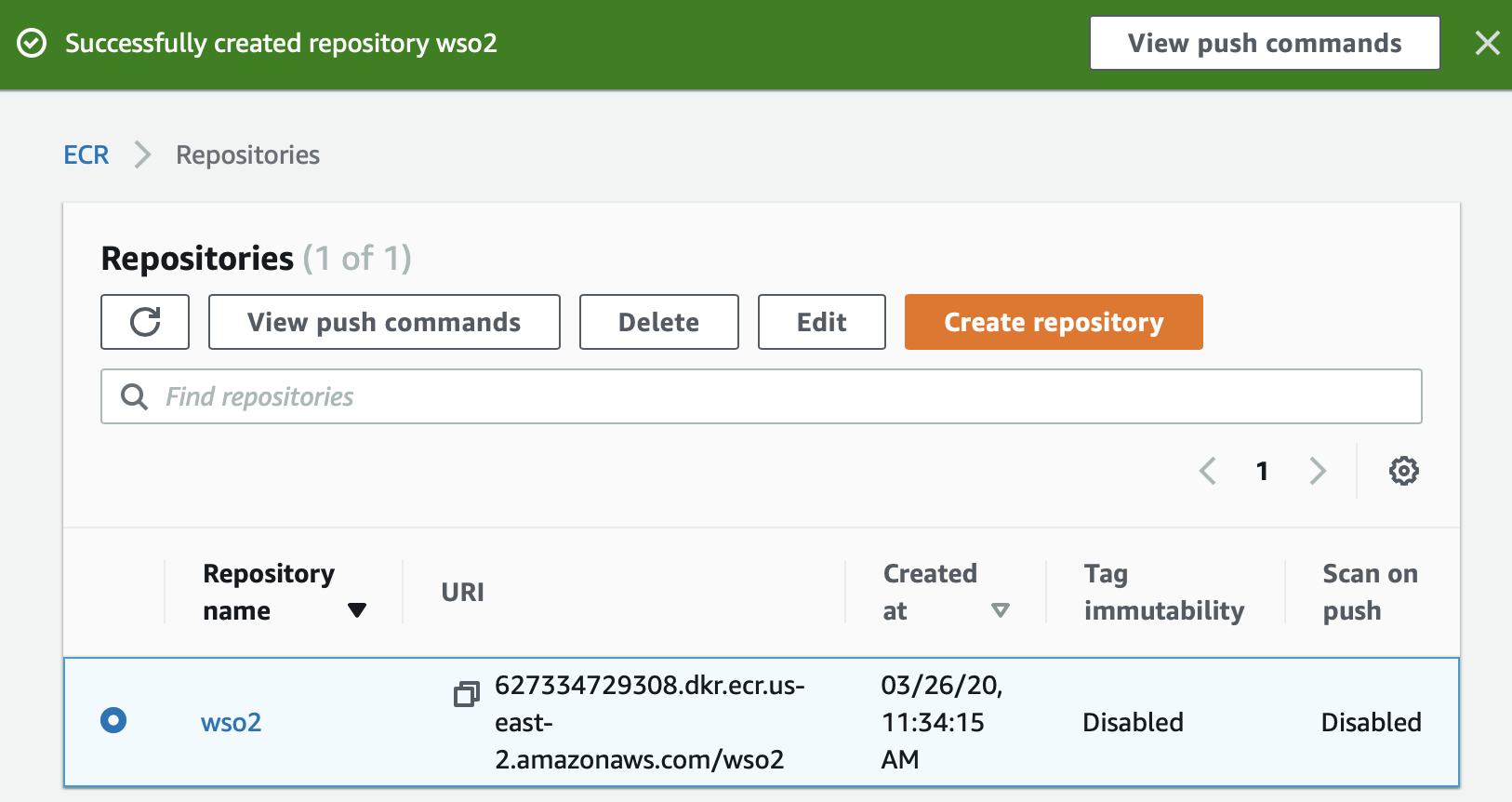
To create a new repository, click Create a repository -> Get Started. The Create Repository page opens.
-
For this example, enter
wso2as the repository name and click Create repository to create the repository.The repository is created as shown below.
-
To retrieve an authentication token and authenticate your Docker client to your registry, do the following:
-
In the Repositories page, click View push commands.
-
Copy the command given under Retrieve an authentication token and authenticate your Docker client to your registry.. This command is similar to the following example.
aws ecr get-login-password --region us-east-2 | docker login --username AWS --password-stdin 627334729308.dkr.ecr.us-east-2.amazonaws.com/wso2 -
Issue the command you copied in the AWS CLI. The following message appears in the CLI.
Login Succeeded
-
-
-
Build Docker images with SI configurations as follows:
-
Edit the
<SI_HOME>/conf/server/deployment.yamlfile as follows.-
In the
state.persistencesection, update the following parameters.Parameter Value enabledtruepersistenceStoreorg.wso2.carbon.streaming.integrator.core.persistence.DBPersistenceStoredatasourcePERSISTENCE_DBtablePERSISTENCE_TABLEClick here to view the updated
state.persistencesection.state.persistence: enabled: true intervalInMin: 1 revisionsToKeep: 2 persistenceStore: org.wso2.carbon.streaming.integrator.core.persistence.DBPersistenceStore config: datasource: PERSISTENCE_DB table: PERSISTENCE_TABLE -
In the
wso2.datasources:section, add two data sources namedPERSISTENCE_DBandWSO2_CLUSTER_DBas follows.- name: PERSISTENCE_DB description: The MySQL datasource used for persistence jndiConfig: name: jdbc/PERSISTENCE_DB definition: type: RDBMS configuration: jdbcUrl: 'jdbc:mysql://wso2db.cxtsxcdgcayr.ap-south-1.rds.amazonaws.com:3306/persistencedb?useSSL=false' username: root password: rootroot driverClassName: com.mysql.jdbc.Driver maxPoolSize: 50 idleTimeout: 60000 connectionTestQuery: SELECT 1 validationTimeout: 30000 isAutoCommit: false- name: WSO2_CLUSTER_DB description: The MySQL datasource used for persistence jndiConfig: name: jdbc/WSO2_CLUSTER_DB definition: type: RDBMS configuration: jdbcUrl: 'jdbc:mysql://wso2db.cxtsxcdgcayr.ap-south-1.rds.amazonaws.com:3306/clusterdb?useSSL=false' username: root password: rootroot driverClassName: com.mysql.jdbc.Driver maxPoolSize: 50 idleTimeout: 60000 connectionTestQuery: SELECT 1 validationTimeout: 30000 isAutoCommit: false -
To enable clustering and update strategy configuration values, update the
cluster.configsection as follows:Parameter Value enabledtruegroupIdsicoordinationStrategyClassorg.wso2.carbon.cluster.coordinator.rdbms.RDBMSCoordinationStrategydatasourceWSO2_CLUSTER_DBheartbeatInterval5000heartbeatMaxRetry5eventPollingInterval5000Click here to view the updated
cluster.config:section.cluster.config: enabled: true groupId: si coordinationStrategyClass: org.wso2.carbon.cluster.coordinator.rdbms.RDBMSCoordinationStrategy strategyConfig: datasource: WSO2_CLUSTER_DB heartbeatInterval: 5000 heartbeatMaxRetry: 5 eventPollingInterval: 5000 -
Uncomment the
deployment.config:section and edit the parameters as follows:
Parameter Value typehahostlocalhostadvertisedHostlocalhost -
-
Clone the
docker-eirepository by issuing the following command.git clone https://github.com/wso2/docker-ei -
In the
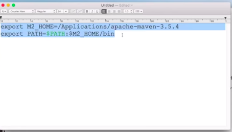
docker-ei/alpine/streaming-integrator/docker-entrypoint.shfile, enter the following code before the# start WSO2 servercomment.Info
In this example, it is assumed that you are using
alpine. You can also usecentosorubuntu.IP=$(ifconfig eth0 | grep "inet addr" | cut -d ':' -f 2 | cut -d ' ' -f 1) DEPLOYMENT_YAML=${WSO2_SERVER_HOME}/conf/server/deployment.yaml echo "$IP" sed -i "s/localhost/$IP/" "$DEPLOYMENT_YAML"This gets the IP address of the host machine and replaces it in the HA configuration in the
<SI_HOME>/conf/server/deployment.yamlfile. -
Make a copy of the
<SI_HOME>/conf/server/deployment.yamlfile you edited and paste it indocker-ei/dockerfiles/alpine/streaming-integratordirectory. -
In the
docker-ei/dockerfiles/alpine/streaming-integrator/deployment.yamlfile, underwso2.carbon:, change value for theidparameter towso2-si-1.id: wso2-si-1 -
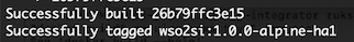
To build the Docker image for node 1, navigate to the
docker-ei/dockerfiles/alpine/streaming-integratordirectory and issue the following command.docker build -t wso2si:1.0.0-alpine-ha1 .Once the build is successfully executed, a message similar to the following appears in the CLI.
-
In the
docker-ei/dockerfiles/alpine/streaming-integrator/deployment.yamlfile, underwso2.carbon, change value for theidparameter towso2-si-2.id: wso2-si-2This is because, now you are using the same repository to build the Docker image for node 2.
-
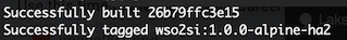
To build the Docker image for node 2, navigate to the
docker-ei/dockerfiles/alpine/streaming-integratordirectory and issue the following command.docker build -t wso2si:1.0.0-alpine-ha2 .Once the build is successfully executed, a message similar to the following appears in the CLI.
-
To tag the built images, issue the following commands.
docker tag wso2si:1.0.0-alpine-ha2 <AWS_ACCOUNT_NUMBER>.dkr.ecr.us-east-2.amazonaws.com/wso2:ha1docker tag wso2si:1.0.0-alpine-ha1 <AWS_ACCOUNT_NUMBER>.dkr.ecr.us-east-2.amazonaws.com/wso2:ha2 -
To push the images, issue the following commands.
docker push <AWS_ACCOUNT_NUMBER>.dkr.ecr.us-east-2.amazonaws.com/wso2:ha1docker push <AWS_ACCOUNT_NUMBER>.dkr.ecr.us-east-2.amazonaws.com/wso2:ha2
-
STEP 2: Create RDS for persisting and clustering requirements
To create a Amazon RDS (Relational Database Service) for the purpose of persisting data handled by the cluster, follow the procedure below:
-
Access Amazon RDS via the AWS console.
-
To add a parameter group and change the value for the
max_connectionsparameter for it, follow the procedure below:-
In the left navigator, click Parameter groups. Then, in the Parameter Groups page, click Create Parameter Group to create a new parameter group.
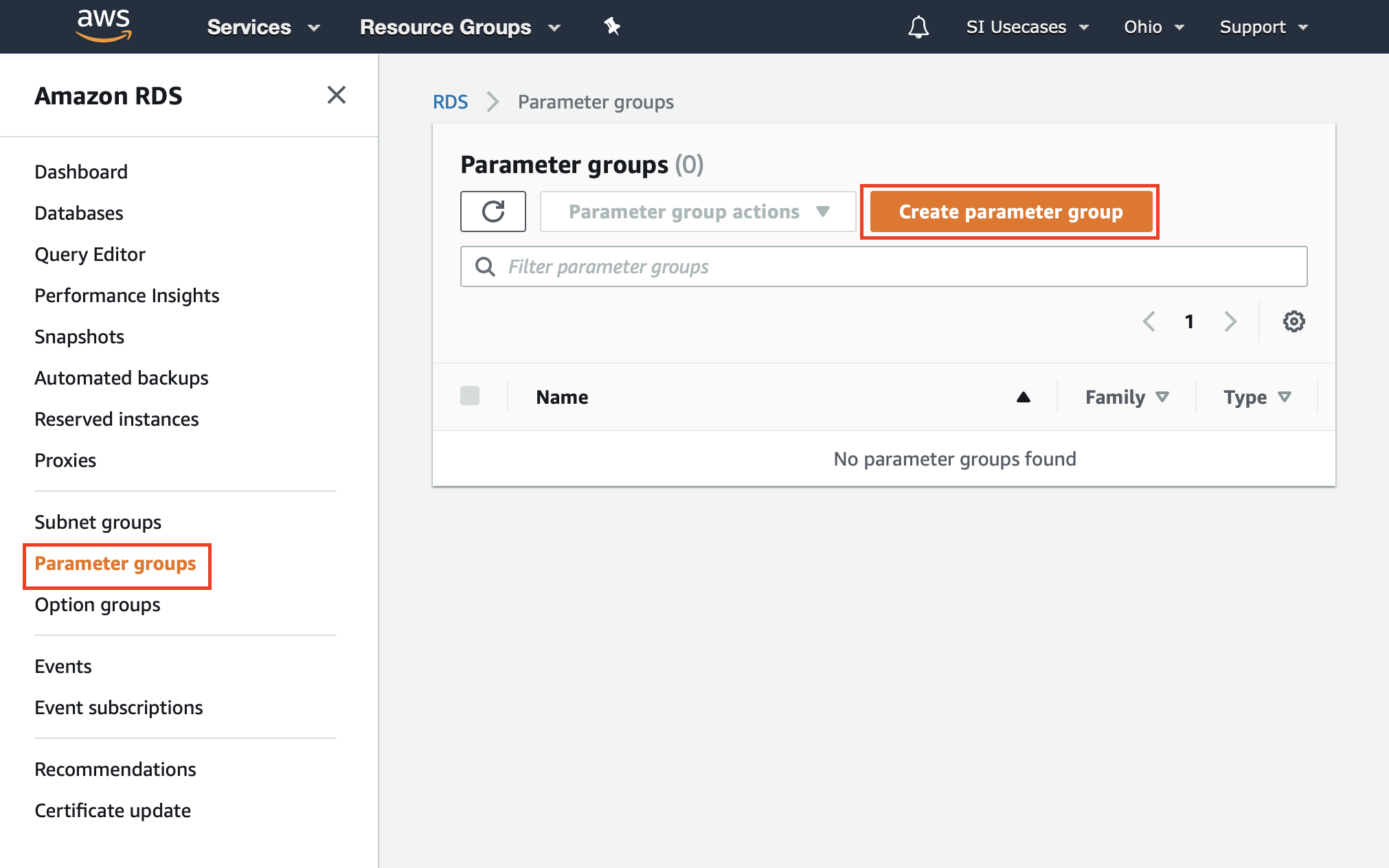
The Create parameter group page opens.
-
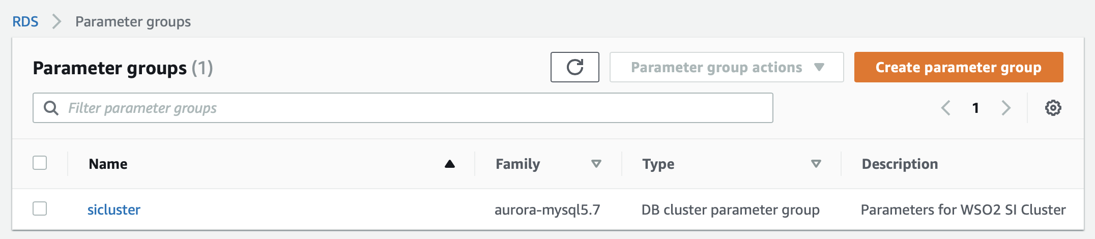
Enter details in the Create parameter group page to create a new parameter group.
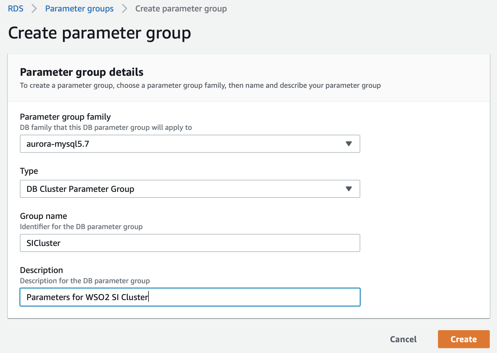
Then click Create. The newly created parameter group appears in the Parameter groups page as follows.
-
To edit the parameter group, click on it. Then search for the max_connections parameter, select it, and click Edit parameters. Change the value for the
max_connectionsparameter to300and then click Save changes.
-
-
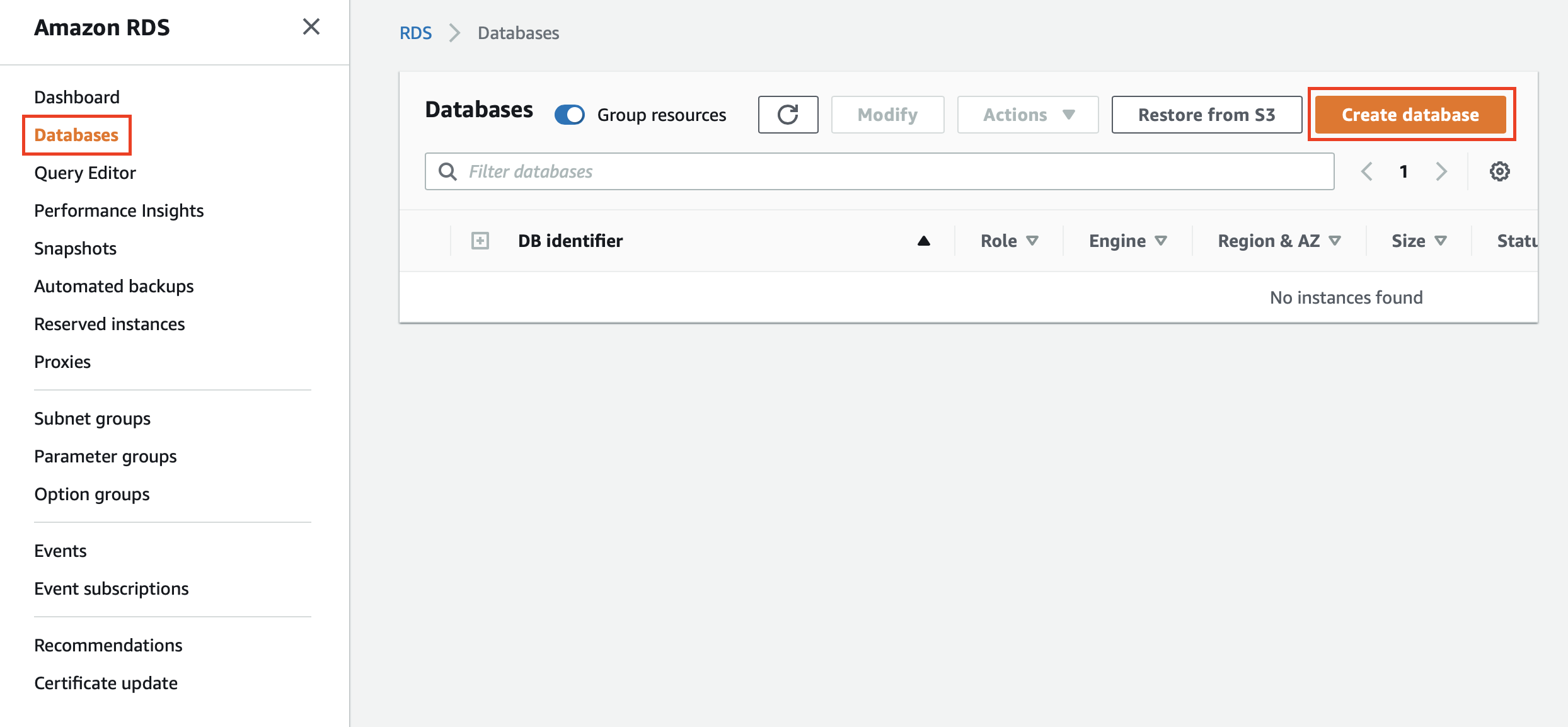
Create an RDS instance as follows:
-
In the left navigator, click Databases. Then in the Databases page, click Create database to open the Create Database page.
-
In the Create Database page, enter details as follows.
-
Select Standard Create.
-
Under Engine Type, select MySQL.
-
Under Templates, select Free Tier.
-
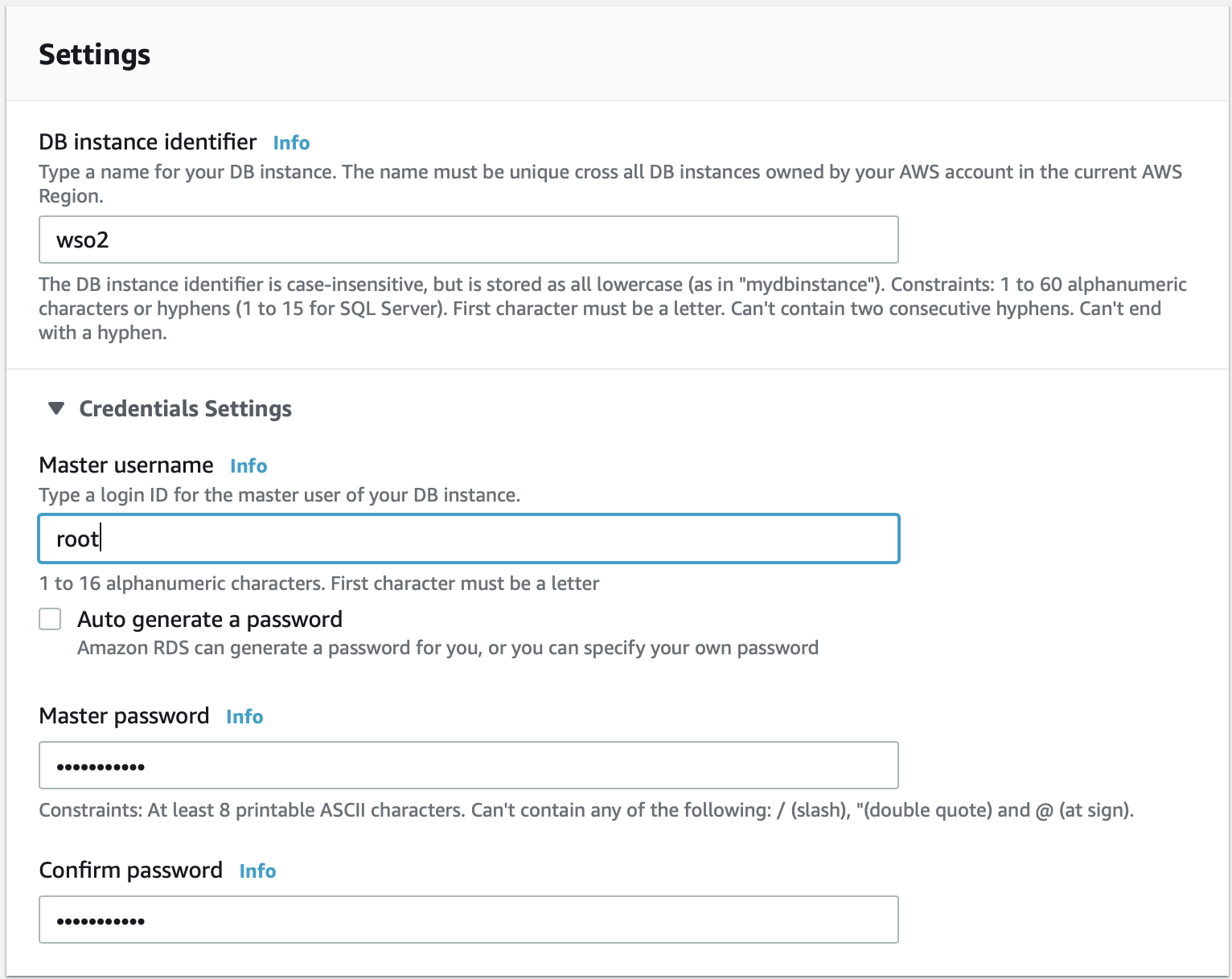
Under Settings, enter details as instructed within the user interface.
-
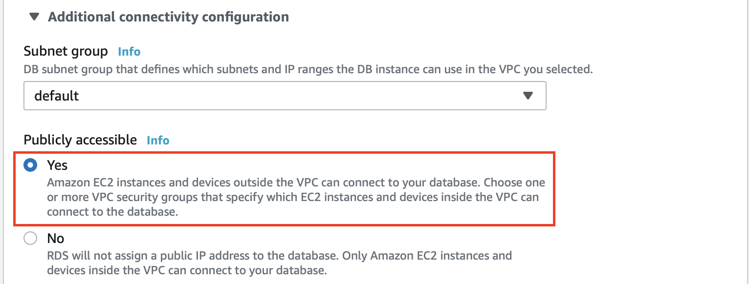
Under Connectivity, expand the Additional connectivity configuration. Under Publicly accessible, select Yes. This allows you to connect and create the database, and then check on the database values later.
-
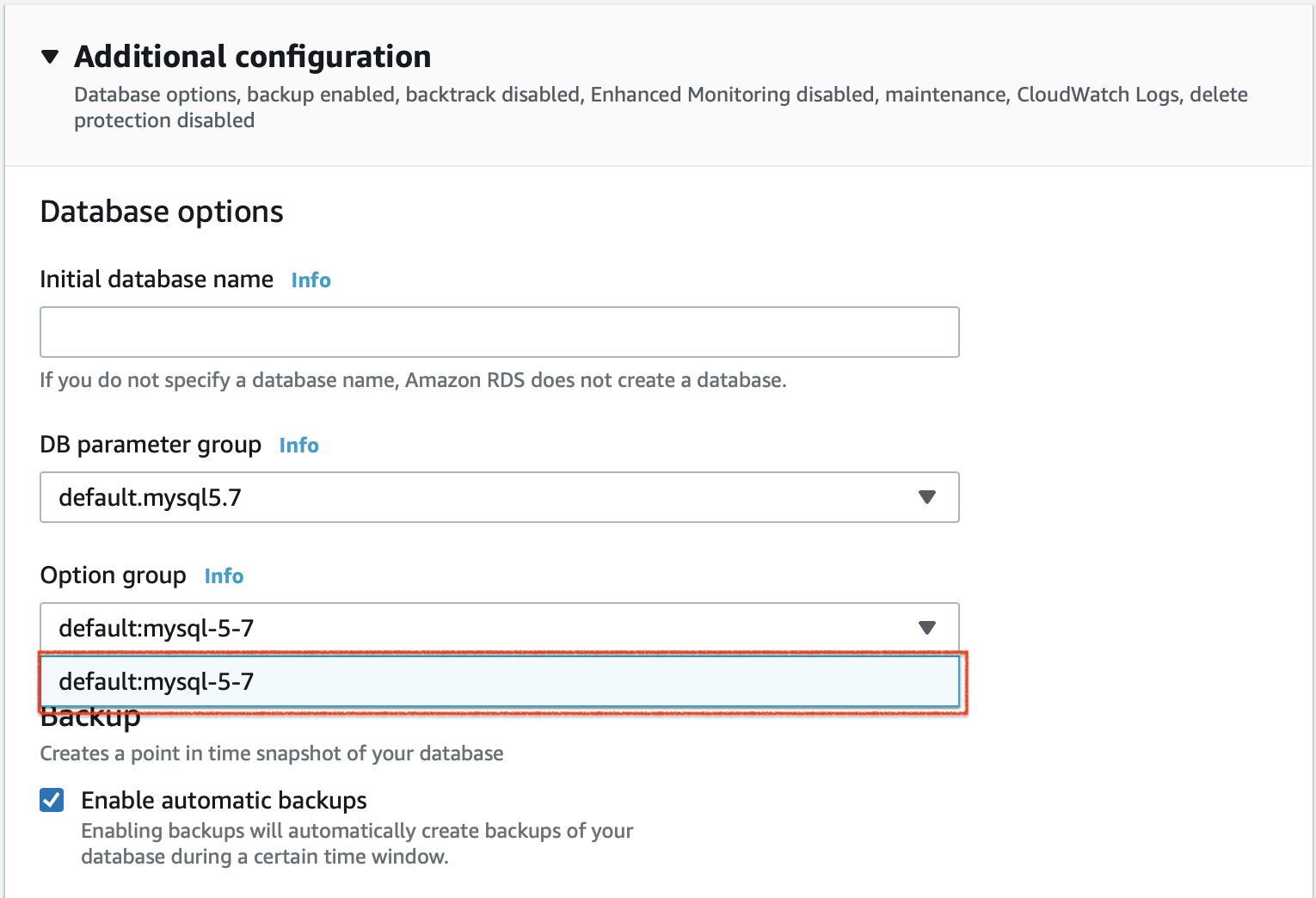
Expand the Additional Configurations section. In the DB parameter group field, select the parameter group that you previously created.
-
Click Create database. The database you created appears in the Databases page.
-
-
Enable public access to the database as follows:
-
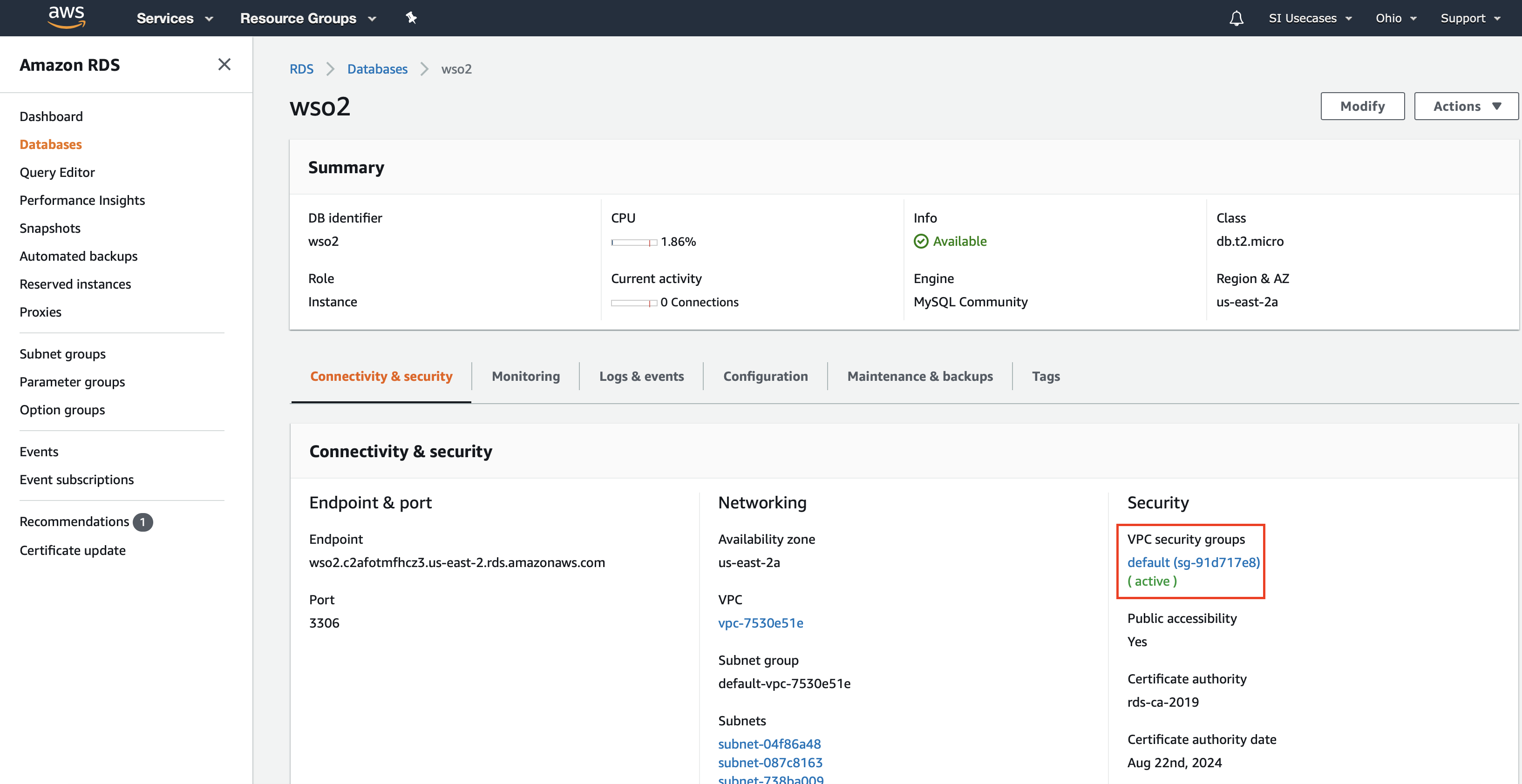
In the Databases page, click on the wso2 database you created to view details of it in a separate page.
-
In the Security section, click the VPC.
-
In the Security Groups page that opens, click on the relevant security group to view details of it in a separate page.
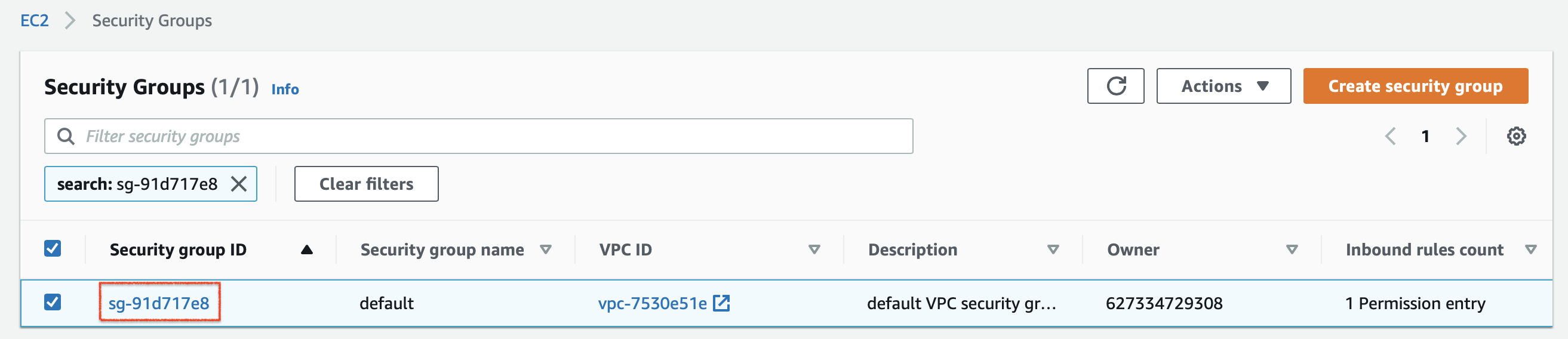
-
In the page with details of your security group, click Edit Inbound Rules.
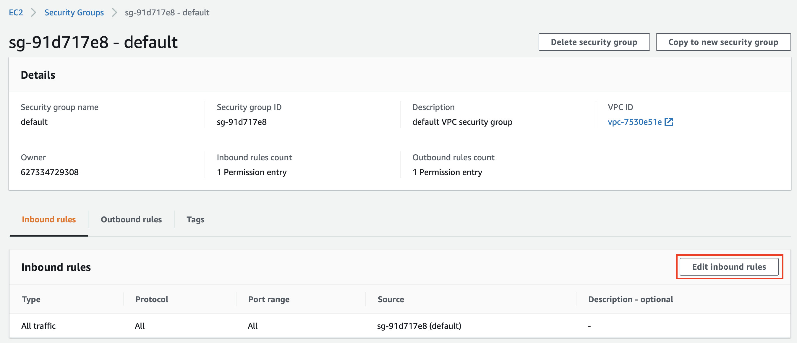
This opens the Edit inbound rules page.
-
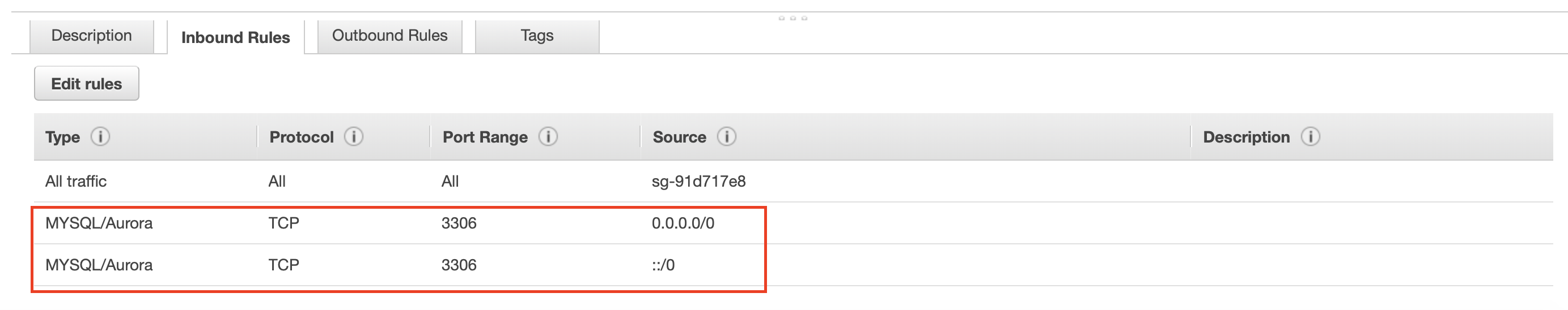
In the Edit inbound rules page, add two rules as follows.
Type Source MYSQL/AURORA Select Custom for the Source field and then select 0.0.0.0/0 as the value. MYSQL/AURORA Select Custom for the Source field and then select ::/0 as the value. Then click Save rules.
-
-
Step 3: Set up ECS cluster, tasks and services
-
To create a VPC (Virtual Private Cloud), a subnet, and a security group, follow the procedure below:
-
Access the VPC Dashboard via the AWS Console.
-
Click Launch VPC Wizard.
-
In Step 1: Select a VPC Configuration, VPC with a Single Public Subnet is selected by default in the left pane. Click Select for it.
-
In Step 2: VPC with a Single Public Subnet, enter
si-ha-vpcin the VPC name field. Then click Create VPC.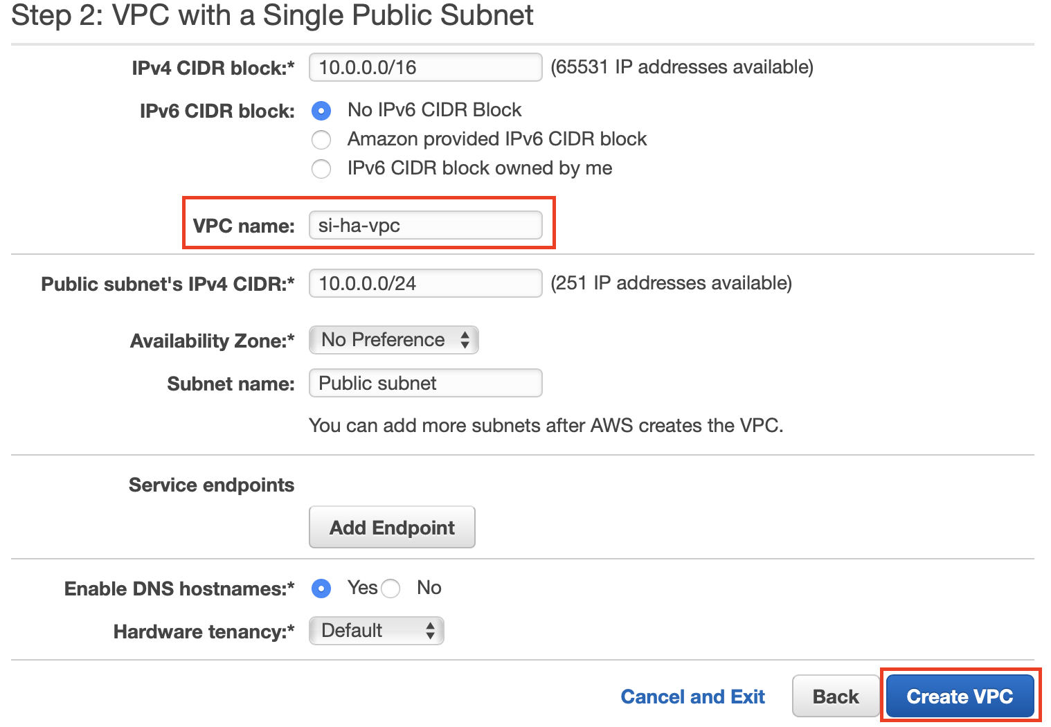
After successfully creating the VPC, you can view it in the Your VPCs page as follows:
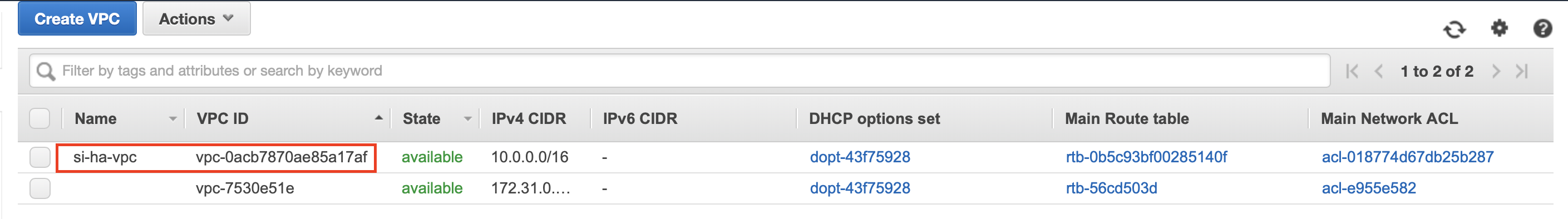
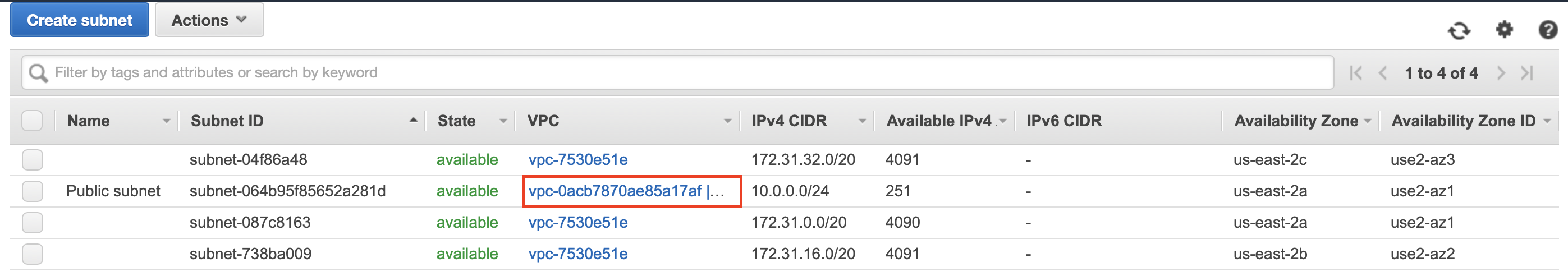
To view the public subnet created, click Subnets in the left navigator. The subnet connected to the VPC is displayed as shown below.
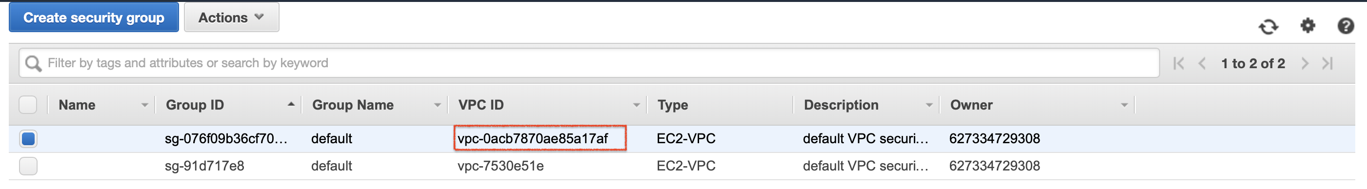
To view the security group of the VPC, click Security Groups in the left navigator. The security group is displayed as follows.
Info
When you select the security group and view details for it at the bottom of the Security Groups page, note that all incoming traffic is currently enabled for now in the Inbound Rules tab.
-
-
Set up the cluster as follows:
To set up the cluster, follow the procedure below:
-
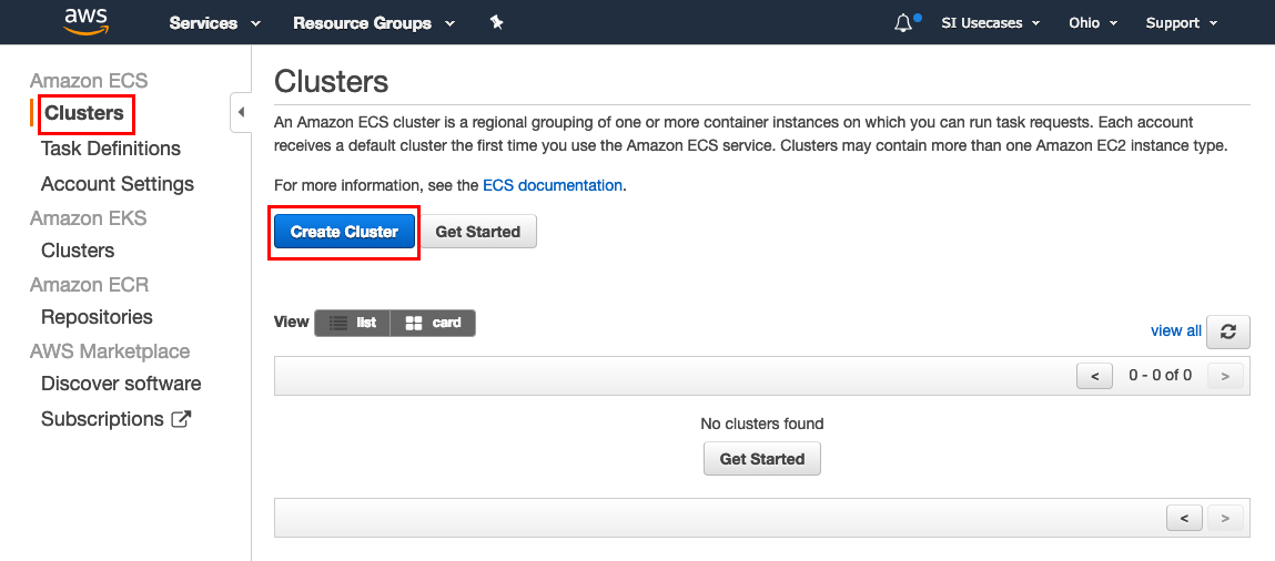
Access Amazon ECS via the AWS Console.
-
In the left navigator, click Clusters. Then click Create Cluster in the Clusters page.
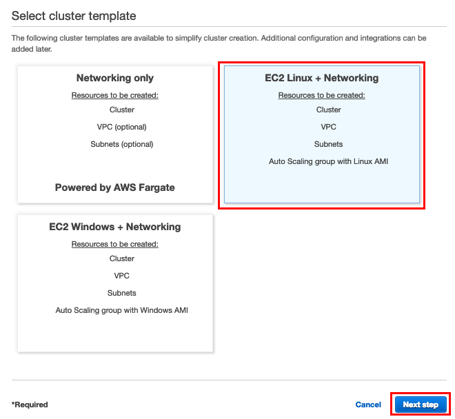
-
In the Create Cluster wizard that opens, select EC2 Linux + Networking and then click Next step.
-
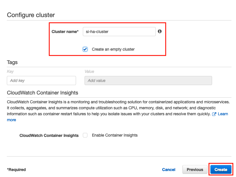
In Step 2: Configure Cluster of the Create Cluster wizard, enter information as follows:
-
In the Cluster name field, enter a name for your cluster. In this example, let's enter
si-ha-clusteras the name. -
Select the Create an empty cluster check box.
-
Click Create to create the cluster.
-
-
-
Create a task for Streaming Integrator node 1 as follows:
-
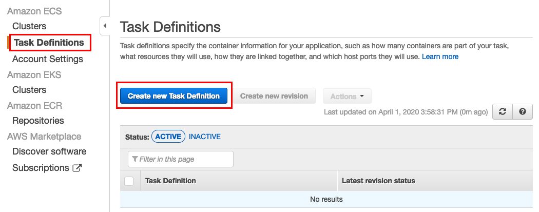
In the left navigator of Amazon ECS, click Task Definitions. Then in the Task Definitions window, click Create new Task Definition.
-
In the Select launch type compatibility page, click FARGATE and then click Next step.
-
In Step 2: Configure task and container definitions, enter information in the Create new Task Definition wizard as follows:
-
In the Task Definition Name field, enter
ha-node-1-taskas the name of the task definition. -
In the Task Size section, enter values as follows:
Field Value Task memory (GB) 0.5GBTask CPU (vCPU) 0.25vCPU -
In the Container Definitions section, click Add container. Then enter information as follows:
-
In the Container name field, enter
node-1-ha-containeras the name of the container. -
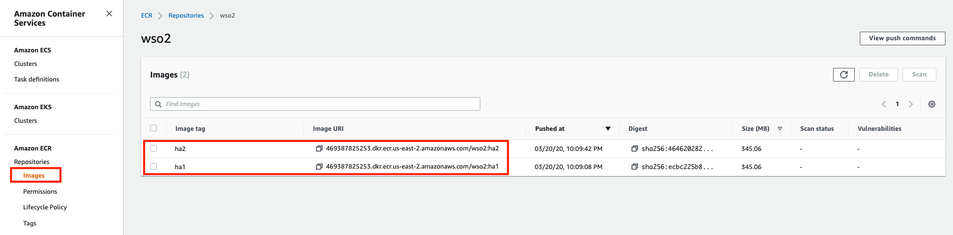
In the Image field, enter the image URI.
Tip
To get the image URI, follow the steps below:
1. Access Amazon ECR via the AWS Console.
2. In the left navigator, click Repositories to open the Repositories window.
3. Click on your repository (which iswso2in this example).
The available docker images are displayed in the Images window.
3. In the Port Mappings section, add the following ports.Port Protocol 9893 tcp 9090 tcp 9711 tcp 9611 tcp 7711 tcp 7611 tcp 7443 tcp 7070 tcp 9443 tcp 8006 tcp To add each port, click Add Port Mapping.
-
Click Add.
-
Click Create in the Configure task and container definitions page to create the task.
-
-
-
-
Create a task for Streaming Integrator node 2 as follows:
-
In the left navigator of Amazon ECS, click Task Definitions. Then in the Task Definitions window, click Create new Task Definition.
-
In the Select launch type compatibility page, click FARGATE and then click Next step.
-
In Step 2: Configure task and container definitions, enter information in the Create new Task Definition wizard as follows:
-
In the Task Definition Name field, enter
ha-node-2-taskas the name of the task definition. -
In the Task Size section, enter values as follows:
Field Value Task memory (GB) 0.5GBTask CPU (vCPU) 0.25vCPU -
In the Container Definitions section, click Add container. Then enter information as follows:
-
In the Container name field, enter
node-2-ha-containeras the name of the container. -
In the Image field, enter the image URI.
-
In the Port Mappings section, add the following ports.
Port Protocol 9893 tcp 9090 tcp 9711 tcp 9611 tcp 7711 tcp 7611 tcp 7443 tcp 7070 tcp 9443 tcp 8006 tcp To add each port, click Add Port Mapping.
-
Click Add.
-
Click Create in the Configure task and container definitions page to create the task.
-
-
-
-
Create a service for node 1 using the
ha-node1-tasktask as follows:-
In Amazon ECS, click Clusters in the left navigator. Then click on your cluster.
This opens the Create Service wizard.
-
In the Step 1: Configure service page, select/enter information as follows:
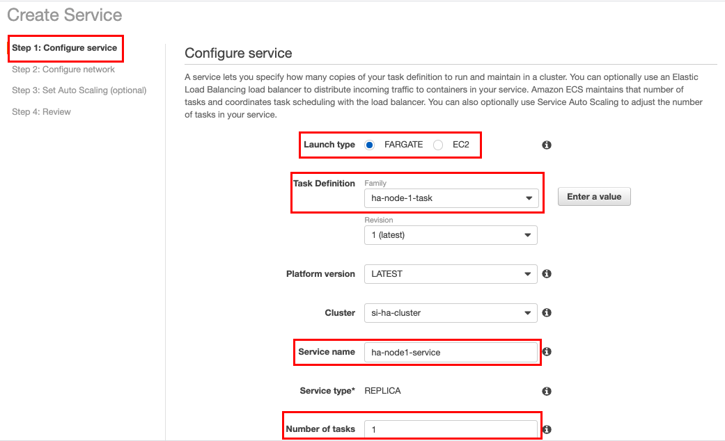
Field Value Launch Type FARGATE Task Definition ha-node-1-task Service Name ha-node1-serviceNumber of tasks 1Then click Next step.
-
In the Step 2: Configure network, select/enter information as follows:
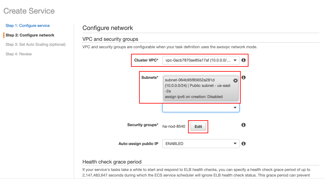
-
In the Cluster VPC field, select the VPC that you previously created.
-
In the Subnets field, select the subnet that you previously created for your VPC.
-
Click Edit to select the security group.
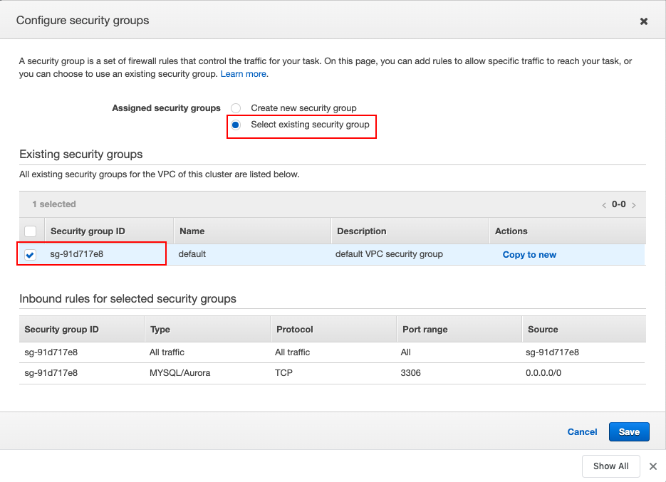
When you click Edit, the Configure security groups dialog box opens. Here, select the Select existing security group option and then select the security group that you previously created and connected to your VPC. Then click Save to save he information you entered in this dialog box.
Once you are back in the Step 2: Configure network page of the Create Service wizard, click Next step.
-
-
Skip Step 3: Set Auto Scaling (optional) by clicking Next step in the page without making any changes. In Step 4: Review, check the information, and click Create Service.
Once the service is successfully created, click View Service to view it. You can also access it by clicking Clusters in the left navigator, and then clicking si-ha-cluster -> Services tab -> ha-node1-service.
-
To view the running service and node logs, follow substeps below:
-
Click Clusters in the left navigator. Then click si-ha-cluster -> Services tab -> ha-node1-service to view the
ha-node1-serviceservice you created. -
Click on the Tasks tab. The task is displayed as shown below.
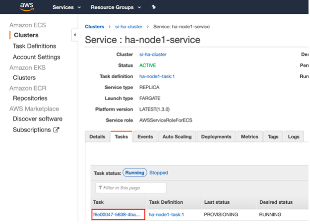
-
Click on the task to view it in a separate page. In that page, click on the View logs in CloudWatch. The following logs should be available to indicate that the node is started in the Active mode and it is persisting events.
    [2020-03-20 20:18:48,283]  INFO {org.wso2.carbon.streaming.integrator.core.ha.HAManager} - HA Deployment: Starting up as Active Node
    [2020-03-20 20:18:52,261]  INFO {org.wso2.carbon.kernel.internal.CarbonStartupHandler} - WSO2 Streaming Integrator started in 44.893 sec
    [2020-03-20 20:19:46,595]  INFO {org.wso2.carbon.streaming.integrator.core.persistence.PersistenceManager} - Siddhi apps persisted successfully
-
-
-
Create a service for node 2 using the
ha-node2-tasktask by following the same procedure you followed in the previous step (i.e., step 5) to create a service for node 1. However, make sure that the task definition isha-node2-task. The service name can beha-node2-service.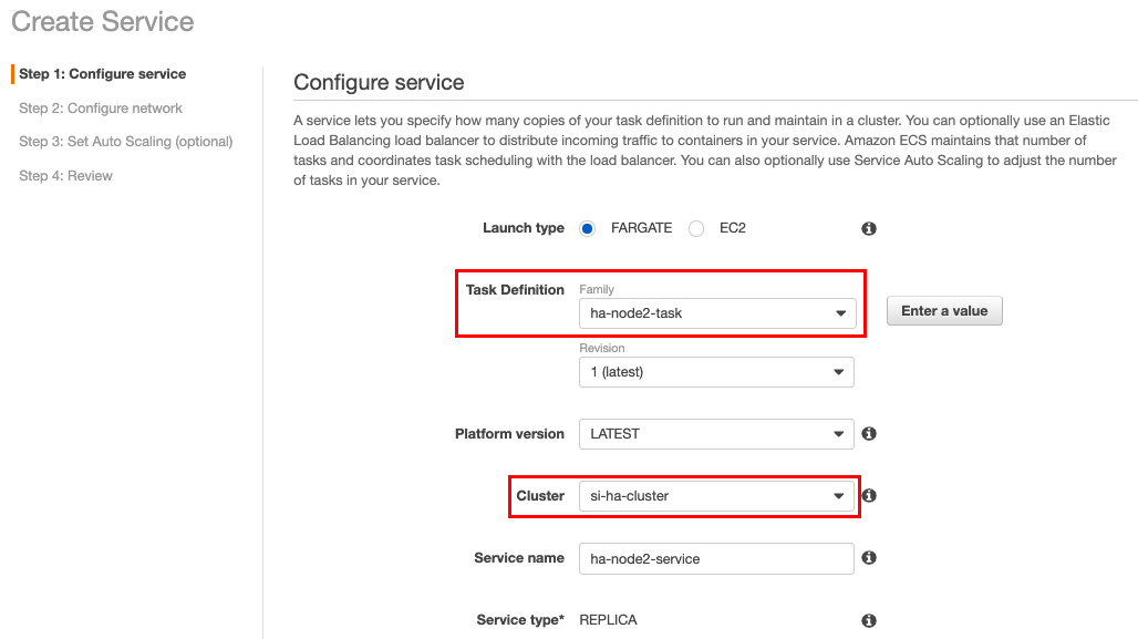
When you view logs in CloudWatch for node 2, the following is displayed.
[2020-03-20 20:38:14,390] INFO {org.wso2.carbon.streaming.integrator.core.ha.HAManager} - HA Deployment: Starting up as Passive Node [2020-03-20 20:38:18,287] INFO {org.wso2.carbon.kernel.internal.CarbonStartupHandler} - WSO2 Streaming Integrator started in 46.604 sec -
To check whether the cluster is working, check logs for node 1 as well as the error trace nodes.
Logs similar to the following should be printed for node 1.
    [2020-03-20 20:38:15,409]  INFO {org.wso2.carbon.streaming.integrator.core.ha.HAEventListener} - memberAdded event received for node id : wso2-si-2
    [2020-03-20 20:38:15,455]  INFO {org.wso2.carbon.streaming.integrator.core.ha.HAEventListener} - Active node retrieved node details of passive node
Also, the following log should be printed without errors by the Error traces.
[2020-03-20 20:38:46,587] INFO {org.wso2.carbon.streaming.integrator.core.persistence.PersistenceManager} - Siddhi apps persisted successfully